Steckplatine Netzteil 5V / 3.3V

Sparkfun ElectronicsArtikelnummer:RB-Spa-105
Hersteller #: PRT-00114

Preis  :
Verkaufspreis €14,19

Steuern inklusive

Versandkosten werden an der Kasse berechnet

Lager  :
Nur noch 1 Einheit übrig

Zahlungen und Sicherheit

Apple Pay Mastercard PayPal Visa

Ihre Zahlungsinformationen werden sicher verarbeitet. Wir speichern keine Kreditkartendaten und haben keinen Zugriff auf Ihre Kreditkarteninformationen.

Beschreibung

Bietet saubere 5V / 3.3V zu Ihrem Steckbrett oder Projekt
erfordert Löten und Montage
Keine Montageanleitung vorhanden

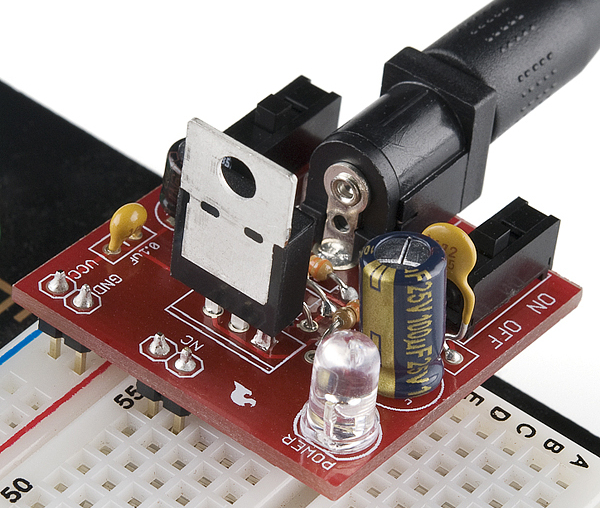
Das SFE Steckplatine Netzteil ist ein sehr einfaches Steckernetzteil , das Strom aus einer DC-Wandversorgung bezieht und eine wählbare Spannung von 5V oder 3,3V ausgibt. Die .1" Header sind auf der Unterseite der Platine montiert, um sie einfach in ein Steckbrett einsetzen zu können. Mit VCC und GND beschriftete Pins werden direkt in die Stromleitungen gesteckt. Das einzelne Pinpaar hat keine elektrische Verbindung, unterstützt aber die Leiterplatte. Zwei Stifte stehen innerhalb des Fassungsraums zur Verfügung. Alle gesteckten +/- DC-Versorgungen können anstelle des Fassanschlusses angeschlossen werden.Das Board hat sowohl einen Ein / Aus-Schalter als auch einen Spannungswahlschalter (3,3 V / 5 V).

Steckernetzteil 5V / 3.3V - Klicken Sie auf Vergrößern

Dieses Produkt wird als Teilesatz geliefert und kann leicht zusammengebaut werden, wenn Sie den Siebdruckanzeigern folgen und etwas Erfahrung mit einem Lötkolben haben. Sie müssen die Widerstandsbänder lesen oder ein Multimeter verwenden, um die Widerstandsgrößen zu bestimmen. Es wird keine Montageanleitung bereitgestellt.

• DC Barrel Connector (2,1 mm Mitte positiv)
• TO-220 Spannungsregler (LM317 1,5A max. Strom)
• 1N4004 Rückwärtsschutzdiode
• 100uF 25V Kondensator
• 10uF 25V Kondensator
• 0.1uF 50V Kondensator
• Rote Power LED - Hohe Helligkeit
• 2pcs SPDT Schiebeschalter
• 4 Stück 0.1 "Header Pins
• 2pcs 330 Widerstand 1 / 6W
• 390 Widerstand 1 / 6W
• 240 Widerstand 1 / 6W
• Blank PCB mit Silkscreen-Indikatoren

  • Empfohlene Stromversorgung: Wand-Adapter Netzteil - 9V Gleichstrom 650mA

Customer Reviews

Based on 8 reviews
75%
(6)
25%
(2)
0%
(0)
0%
(0)
0%
(0)
M
Mr Magoo
Easy to Build but some observations

This circuit is easy to build, but since it does not come with a build sheet; besides soldering experience you should have access to resistor color code information (for correct placement of resistors). The only other component that is tricky to place is the Power LED which must be installed in the correct orientation (not marked like electrolytic caps; lead length is the clue). You best test the LED to determine the + pin orientation before soldering in place. I also found the output voltages to be 3.21 (for 3.3 setting) and 4.88v (for 5V setting). The last comment is that the breadboard pins are in line on the circuit board, but when you plug into the solderless breadboard the power bus lines are offset slightly which means the power supply board does not sit square on the breadboard (not a big issue just an observation). It would have been nice if the circuit board offset the breadboard output pins to match the breadboard.

k
kcwcc
Works as expected

3.3 and 5 V. Fit's standard BB. Must be assembled from a kit. Short circuit protected. Works.

R
Robert
Works Great!!

Works great, fairly simple to assemble as long as you can solder.

M
Mr Magoo
Facile à construire mais quelques observations

Ce circuit est facile à construire, mais comme il n’est pas accompagné d’une feuille de construction; en plus de l'expérience de la soudure, vous devez avoir accès aux informations du code de couleur des résistances (pour un placement correct des résistances). Le seul autre composant qui soit difficile à placer est le voyant d'alimentation qui doit être installé dans le bon sens (non marqué comme les capuchons électrolytiques; la longueur de fil est l'indice). Il est préférable de tester le voyant pour déterminer l’orientation de la broche + avant de souder en place. J'ai aussi trouvé que les tensions de sortie étaient 3.21 (pour le réglage 3.3) et 4.88v (pour le réglage 5V). Le dernier commentaire est que les broches de la planche à pain sont alignées sur le circuit imprimé, mais lorsque vous branchez la carte à pain sans soudure, les lignes du bus d’alimentation sont légèrement décalées, une remarque). Cela aurait été bien si le circuit imprimé compensait les broches de sortie de la planche à pain pour correspondre à la planche à pain.

R
Robert
Fonctionne très bien!!

Fonctionne très bien, assez simple à assembler aussi longtemps que vous pouvez souder.

Versand schätzen

Das könnte Ihnen auch gefallen